Resilience Modelling is a process for identifying opportunities to improve the resilience of a system. This process takes the concepts from the “AWS Resilience Analysis Framework” and applies a treatment similar to Threat Modelling. This framework enables us to cultivate a culture of continuous improvement through consistent, repeatable standards and processes. The Resilience Modelling process is for individuals who already have an awareness or knowledge of SLOs, Error Budgets, RTOs and RPOs. It assumes a level of architectural maturity that would include the existence of, or the ability to create, architectural diagrams and key journey flows. Resilience Modelling helps bring this knowledge together in a practical manner to identify opportunities for improvement in the resilience profile of a system or collection of systems, and to prioritise these improvements.
This process outlines how to identify faults in a system by leveraging well-defined failure modes against architectural models, followed by a series of practical steps to automate the detection of these faults, remediate them, and prevent future faults. This approach applies to a range of systems, including front-end, cloud-based, on-premise, data pipelines, build pipelines, products and platforms. This process is part of a feedback loop designed to be repeated, allowing for a more thorough application of the treatments while also adapting the treatments to the evolving system and environment.
The Resilience Analysis Framework identifies five key properties of a highly available distributed system, each mapped to a failure category.
| Failure category | Violates | Definition |
| Shared fate | Fault isolation | A fault that’s caused by any of the previous failure categories crosses intended fault isolation boundaries and cascades to other parts of the system or other customers. |
| Excessive load | Capacity | Over-consumption of a resource, resulting from excessive demand or traffic, prevents the resource from performing its intended function. This can include reaching limits and quotas, which cause throttling and rejection of requests. |
| Excessive latency | Timeliness | System processing or network traffic latency exceeds the expected time, service-level objectives (SLOs), or service-level agreements (SLAs). |
| Misconfiguration and bugs | Output correctness | Software bugs or system misconfiguration that lead to incorrect output. |
| Single points of failure (SPOFs) | Redundancy | A failure in a single component can disrupt the system due to the lack of redundancy for that component. |
The failure categories can be made into a mnemonic SEEMS:
- Shared fate
- Excessive load
- Excessive latency
- Misconfiguration and bugs
- Single point of failure
The properties that the failure categories violate can also become the mnemonic FACTOR:
- Fault isolation,
- (Availability),
- Capacity,
- Timeliness
- Output correctness and
- Redundancy
It SEEMS we have the resilience FACTOR!
There are four main phases to the Resilience Modelling process

Each phase can be completed in isolation as an organisation’s resilience culture matures.
Fault Identification

The first step of Resilience Modelling is to identify the various fault and failure modes in a system. Use the set of resilience “FACTOR” properties to help guide the process of building a resilient system. When a desired property is violated, it can cause a workload to be, or perceived as, unavailable. Using the provided Resilience Modelling worksheet, utilise predefined failure categories and subcategories to help identify various fault and failure modes for the system.
Modelling and diagramming
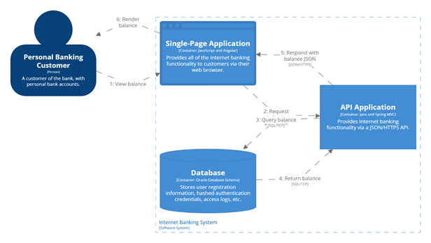
Attempting to define all failure modes for a system may seem overwhelming. Instead of trying to tackle the whole system at once, look to break it down in a structured and repeatable manner. The proposed process here is to leverage a system’s defined critical journeys and its architecture diagrams as a guide in solving the most important things first. The C4 Model has proven to be an effective tool for providing architecture diagrams in this process. Sequence Diagrams, Data Flow Diagrams or Process flow diagrams can be used to support C4 architecture diagrams.
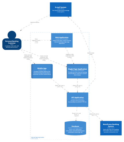
Example C4 Model for an Architecture Diagram C4Model.com and https://structurizr.com/dsl
Example of a simple user journey
Prioritisation through criticality
To effectively prioritise the resilience modelling work, the criticality of each journey and system in that journey should be understood. Each organisation will have their way of classifying how critical a system is.
Some prefer descriptive language to classify systems.
| Criticality Level | Example Impact | Resilience Strategy |
| Mission Critical | Life safety, massive financial/legal loss | Multi-region, automated recovery, <1 min RTO |
| Business Critical | Revenue loss, customer trust damage | Multi-AZ redundancy, automated failover |
| Important | Productivity impact, limited revenue effect | Multi-AZ preferred, backup/restore acceptable |
| Non-Critical | Internal tools, minor disruptions | Best-effort recovery, manual processes |
Others may prefer a less emotive level numbering. This focuses more on the prioritisation than the description.
| Tier | Purpose | Target Availability | Notes |
| Tier 1 | Mission-critical, external users | 99.99%+ (e.g. 5 min/month) | Needs strong redundancy, tight monitoring |
| Tier 2 | Business-critical, revenue-driving | 99.9%+ | Can tolerate short downtimes |
| Tier 3 | Internal, non-customer-facing | 99% | Relaxed SLOs, acceptable degradation |
| Tier 4 | Experimental / dev environments | Best effort | No formal SLOs |
Example Fault Identification Exercise
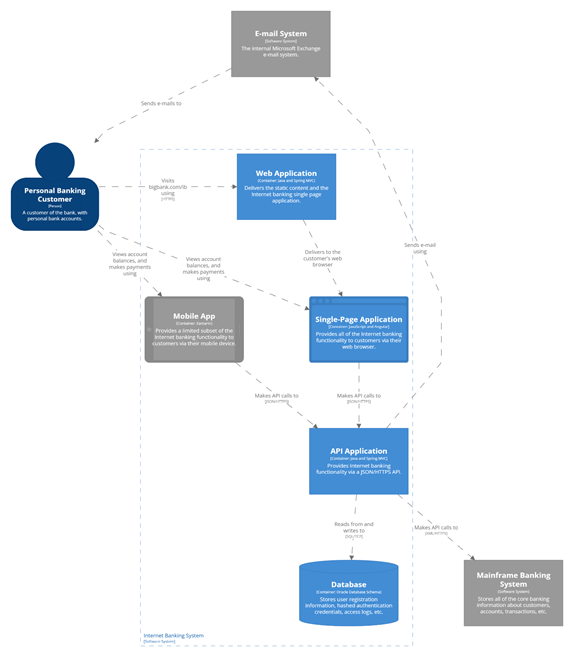
For the example architectural diagram above, it has been defined that email, mobile, and the mainframe are not critical systems for the workload. This was decided because users who can log in to the web application will be able to view their recent balances and request transactions without needing the mobile app, email confirmation, or end-to-end processing from the mainframe. In this diagram, systems not included in the key flows are indicated by marking them as non-critical, colouring them grey.
Working through prioritised journeys, use a worksheet as a prompt. Use the provided worksheet to catalogue key journeys, the systems in those journeys and the various failure modes of those systems. The table below shows a partially complete worksheet for the View Balance journey.
| Journey | System | Failure Category | Failure mode | Example |
| Login | Web Application | |||
| Login | Single Page Application | |||
| Login | API Application | |||
| Login | Database | |||
| View Balance | Web Application | Misconfiguration | User tracking is incorrectly captured | Misconfiguration results in either all customer or no customer tracking data being captured, ignoring the consent settings |
| View Balance | Single Page Application | Excessive latency | Large page loads could breach the target page load time of 4s | Unoptimised images or excessive dynamic 3rd party content could cause Web Vital scores to drop to where customers would abandon the journey |
| View Balance | API Application | Shared Fate | Synchronous calls bind the availability of the API Application and the DB | If the DB is degraded or unavailable, the Web API will also be degraded or unavailable |
| View Balance | API Application | Excessive Load | Excessive load would degrade the experience for all users. | When an excessive load is generated from a marketing campaign or a DDoS attack, all users across all flows will experience degraded service. |
| View Balance | Database | Single Point of Failure | A database failure would cause a complete journey outage | During a downtime patching of the database, the entire flow will be offline. |
Note that in the example above, two journeys are defined, with each system involved in the journeys. For the Login journey, each system has at least one failure mode, accompanied by a supporting example. The goal is to capture a reasonable set of failures for each system. Use the failure categories to trigger discussion with the team on how each system in the journey could be affected by each failure mode. There may be multiple failure modes for a single system. It is possible to have various failure modes for the same failure category and different categories.
Unknown unknowns
For deeper investigations that usually occur on subsequent revisions of the Resilience Modelling process, look to identify “unknown unknowns”. Initial investigations may only surface the superficial or obvious failure modes in the system. To look for deeper or non-obvious failure modes, lean on the C4 models to move up and down zoom levels between system, container and component. Utilise historical incident reports to help identify contributing causes that have yet to be documented. Dependency mapping tools can help identify system dependencies, data flows, and artefact dependencies, which can uncover further faults and failure modes.
A checklist may also be helpful to stimulate creative thinking and collaboration to identify contributing causes to failures. The following could serve as an example checklist that can be modified to be more appropriate for the systems in focus (e.g., Mobile, On-Prem, Data, etc.).
- Unreachable
- Network outage
- Misconfiguration of ISP, CDN, DNS, Gateway, Routes, Load Balancer
- Unavailable
- Compute is down
- Datastore is unavailable
- Host fails (server, data centre, region)
- Cost limit hit
- Failed deployment
- Misconfigured deployment
- Certificate expired
- Tightly coupled to other services that are unavailable
- Under serving
- Excessive latency/response time
- Partial outage (30% served at SLA, 70% fail SLA)
- Bi-modal behaviour (works one way under nominal conditions, another way in failure mode conditions)
- Denial of Service
- Scaling up happens too slowly
- A service limit or rate limit is reached
- Routing away from unhealthy nodes is ineffective
- The deployment/fault Isolation unit isn’t sized correctly to support sustained load under fault or deployment
- Multiple use-cases are triggered simultaneously, causing unexpected spikes
- Over serving
- Internal loop creates a self-denial of service
- Wasting resources on work that will never succeed
- Wasting resources on work that will never be used (cancelled tasks, users left, account closed)
- Unbounded queues
- Scaling down happens too slowly
Fault identification is the hardest part of the journey. It requires coordinating the prerequisites and the team to ensure they feel motivated and prepared enough to engage in the process. The good news is that once this process is initiated, the following phases become easier.
Fault identification prerequisites
- Clear definition of criticality levels to be applied
- Journeys for the system are documented and assigned a criticality
- Architectural and flow diagrams for the system
- Fault Identification worksheet
- 1 hour available for the team to collaborate
- An SRE to guide the team through the process
- Optional: list of current alerts for the system
- Optional: read AWS Resilience analysis framework’s Applying the framework section.
Fault identification activities
- Start by identifying one of the most critical journeys
- Identify the architectural and flow diagrams relevant to that journey
- Using the Fault Identification worksheet, identify as many possible fault or failure modes for the first component that is involved in the journey
- Repeat for each of the following components in the journey.
- Repeat as time allows, moving down the criticality of the journeys
Resilience Modelling Worksheet download (Microsoft Excel template file).
Note that this exercise focuses on identifying faults, rather than attempting to automate detection, remediation, or prevention of the issues. This is just a brainstorming exercise. Try to avoid “editing” while working; instead, aim to produce as much content as possible in the allotted time.
Fault Identification post-session activities
- Edit – Now that the session is over, a custodian should look to clean up the worksheet. This is the chance to edit, format and organise the content.
- Complete – Time should be allocated for the team to complete the exercise for all journeys in the agreed criticalities.
- Detection – Book in the next session to design the detection mechanisms for the components.
Fault detection

Once faults have been identified, it’s common to feel the urge to start fixing and redesigning the system immediately. However, resolving all reliability gaps is unlikely to happen quickly. Rushing into remediation risks staying vulnerable to future issues. The second step of the Resilience Modelling process involves implementing detection mechanisms that pinpoint potential or existing workload faults. These detection mechanisms are generally faster to implement than remediation mechanisms and will remain relevant even after improvements in resilience, enabling continuous prioritisation of reliability focus areas.
Fault detection leans on two observability dimensions: leading indicators and lagging indicators. Lagging indicators indicate when a fault has occurred. These are likely to be a breach of a Service Level Objective (SLO) or exhaustion of an Error Budget. Leading indicators provide forewarning that a fault is expected to occur. For example, database timeouts may be a lagging indicator, but rapidly rising database connection counts may be a leading indicator of database timeouts. Lagging indicators tend to be easier to define, measure and alert on.
MELT is another handy mnemonic to remember the types of observability features that can be added to the systems. Metrics, Events, Logs and Traces (MELT) offer different ways to monitor a system. This Observability (O11y) data can be fed into systems to provide dashboards and alerts, visualising and triggering action. Alerts may be triggered based on static, well-defined thresholds or utilise dynamic anomaly detection mechanisms. For example, a static threshold may be defined for an SLO, “99.9% of GET requests will complete in less than 100ms”, but it may be supported by a dynamic anomaly detection set up for the number of requests per second, which may fluctuate in a daily and weekly cycle.
Example fault detection exercise
Continuing from the previous fault identification exercise, extend the worksheet to include the Fault Detection activity columns. For each failure mode, identify the lagging metric that detects that the fault has occurred. If possible, also provide a metric for the leading indicator that detects when a fault is about to occur.
| Journey | System | Failure Category | Failure mode | Example | Lagging Metric | Leading Metric |
| View Balance | Web Application | Misconfiguration | User tracking is incorrectly captured | Misconfiguration results in either all customer or no customer tracking data being captured, ignoring the consent settings | Consented session @ <30% or >90% | Automated deployment tests for consent succeed. |
| View Balance | Single Page Application | Excessive latency | Large page loads could breach the target page load time of 4s | Unoptimised images or excessive dynamic 3rd party content could cause Web Vital scores to drop to where customers would abandon the journey | Journey completion rate <70% | LCP paint > 3s for >10% users |
| View Balance | API Application | Shared Fate | Synchronous calls bind the availability of the API Application and the DB | If the DB is degraded or unavailable, the Web API will also be degraded or unavailable | DB connection errors/second > 3 for 10 seconds | Increase in concurrent requests Increase in HTTP 500/503 errors |
| View Balance | API Application | Excessive Load | Excessive load would degrade the experience for all users. | When an excessive load is generated from a marketing campaign or a DDoS attack, all users across all flows will experience degraded service. | 503/504 HTTP return code > 1% of traffic | Response time > 1s for 10% users Concurrent request > 1000 |
| View Balance | Database | Single Point of Failure | A database failure would cause a complete journey outage | During a downtime patching of the database, the entire flow will be offline. |
When repeating the Fault Detection exercise as part of a routine follow-up, it will be much quicker to move through the process. However, when repeating the exercise, extend the activity to review the metrics for their suitability and efficacy. Ask the question, are these the correct metrics to be tracking, and if so, are they being measured and alerted on effectively? Collaborate with marketing and customer service to see if they can share any insight as to the suitability and efficacy of the existing fault detection processes. Verify that the system metrics support their KPIs, such as cost of acquisition (CAC, CPI), lifetime value (LTV), first response time (FRT), and handle time. In repeat exercises, consider exploring more advanced techniques, such as distributed tracing, service mesh observability, real-user monitoring (RUM), or AI/ML-driven anomaly detection. These techniques can provide a deeper understanding of where failures are happening and why. They can also offer earlier warning signals by identifying leading metric breaches earlier.
The Fault Detection exercises will enhance both the team and the systems. The team will gain a deeper understanding of how the system affects the business and the essential metrics they need to consider. This awareness will enable them to create improved solutions in the future. The system itself will evolve as unknown unknowns (metrics that the team was unaware of the need to track) and unknown knowns (metrics that only a few are aware of tracking) become recognised knowns through a formalised process and documentation.
Fault detection prerequisites
- Journeys for the system are documented and assigned a criticality
- Architectural and flow diagrams for the system
- Completed Fault Identification worksheet (to extend with detection)
- 1 hour available for the team to collaborate
- An SRE to guide the team through the process
- Optional: list of current alerts for the system
- Optional: review guidance on defining failure mode observability or system KPIs
Fault detection activities
- Using the Fault Identification worksheet, identify ways to detect that the identified failure or fault mode is happening or is about to happen.
- Repeat for each of the following components in the journey.
- Repeat as time allows, moving down the criticality of the journeys
Note that this exercise focuses on detecting faults that occur in the system. The focus is not on designing the remediation or prevention of the issues. This is just a brainstorming exercise. Try to avoid “editing” while working; instead, aim to produce as much content as possible in the allotted time.
Fault detection post-session activities
- Edit – Now that the session is over, a custodian should look to clean up the worksheet. This is the chance to edit, format and organise the content.
- Complete – Time should be allocated for the team to complete the exercise for all journeys in the agreed criticalities.
- Execute – Time should be allocated to the implementation of the detection mechanisms.
- Remediation – Book in the next session to design the remediation mechanisms for the system components.
Fault response and remediation

After ensuring that detection mechanisms are in place, move to the third step of the Resilience Modelling process: Fault Response and Remediation. This third step provides a structured approach to defining the methods for responding to faults when they are detected.
When a fault is detected with a leading or lagging metric, it should be accompanied by clear direction on the actions to take. Initially, these actions may be manual and evolve into an automated or self-healing system. However, it can be prudent to invest in automation only if there is a sufficient return on investment. When considering the return on investment for resilience initiatives, adopt a proportional response that aligns with business value and stakeholder priorities. This means engaging with non-technical stakeholders (e.g., product owners, finance, legal, marketing) to translate technical resilience improvements into terms they understand, such as reduced revenue loss, improved customer satisfaction (CSAT scores), decreased operational costs, compliance adherence, or enhanced brand reputation. By framing the investment in resilience in terms of tangible business outcomes and risks, teams can ensure that the level of effort and automation applied is proportional to the potential impact of a failure, securing the necessary buy-in and resources.
Remediation is not the only response to a fault. Response actions can take four forms:
- Remediate – apply corrective measures to resolve the faulty behaviour
- Deactivate – remove the service, feature, or functionality, e.g. feature toggle it off
- Communicate – manage expectations, if the fault cannot be controlled
- Eliminate – remove the alert if it is no longer useful
Example fault response and remediation exercise
Extend the work on the fault detection exercise by providing appropriate responses for each failure mode. This is an opportunity to be creative and think of ways to respond that are both effective and low-cost.
some columns omitted for presentation
| Journey | System | Failure mode | Example | Lagging Metric | Response Category | Response |
| View Balance | Web Application | User tracking is incorrectly captured | Misconfiguration results in either all customer or no customer tracking data being captured, ignoring the consent settings | Consented session @ <30% or >90% | Remediate | Identify the recent release where the behaviour changed. Roll back or roll forward. |
| View Balance | Single Page Application | Large page loads could breach the target page load time of 4s | Unoptimised images or excessive dynamic 3rd party content could cause Web Vital scores to drop to where customers would abandon the journey | Journey completion rate <70% | Remediate | Identify the recent release where the behaviour changed. Roll back or roll forward. |
| View Balance | API Application | Synchronous calls bind the availability of the API Application and the DB | If the DB is degraded or unavailable, the Web API will also be degraded or unavailable | DB connection errors/second > 3 for 10 seconds | Remediate | Failover to the reader-node. |
| View Balance | API Application | Excessive load would degrade the experience for all users. | When an excessive load is generated from a marketing campaign or a DDoS attack, all users across all flows will experience degraded service. | 503/504 HTTP return code > 1% of traffic | Communicate | Due to the absence of DDoS protection, communicate internally to the Marketing team and externally on social media that the system is experiencing high load. |
| View Balance | Database | A database failure would cause a complete journey outage | During a downtime patching of the database, the entire flow will be offline. | 503 HTTP code | Communicate | Provide advance notice about planned outages and maintain open communication internally and externally during the outage. |
When repeating the Fault Response and Remediation exercise as part of a routine follow-up, review the existing responses for their suitability and efficacy. Use recent Post Incident Reviews to provide insight and evidence on the quality of the responses to faults.
The Fault Response and Remediation exercise may surface gaps where the team are unable to define a suitable response to a fault during the exercise. Work with stakeholders and SREs after the exercise to collaboratively identify an appropriate course of action in the event of a fault. With the definition of the responses complete, time will need to be allocated to implement the supporting structures for these mechanisms.
Incident response training
Alerts and Dashboards will need to be tested, as will the response to the alerts. Other supporting materials, such as runbooks, should be peer-reviewed and ideally also tested in Incident Response Training sessions. To further understand and verify fault detection and response processes, consider simulated events such as Game Days, where impulses and stresses to the system, as well as faults within the system, can be tested in a controlled manner. Simulate a transient impulse by sending a rapid shock to the system in the form of a sudden burst of traffic. Impulses can uncover scalability issues, memory limits, cache limits and bounded or unbounded queues. Simulate persistent stress on the system by performing a soak test of sustained traffic. Stresses can uncover disk capacity limits, cache size limits, the impact of garbage collection, and the impact of automated database maintenance (e.g., indexing, vacuum, materialisation, etc.). Simulate faults in the system to observe the actual behaviour in that fault mode. Simulating faults uncovers chain reactions, cascading failures and amplification loops. Look to existing practices such as Fault Injection testing, Chaos Engineering, and Disaster Recovery Testing for structured and specific guidance.
Fault response and remediation prerequisites
- Journeys for the system are documented and assigned a criticality
- Architectural and flow diagrams for the system
- Completed Fault Identification + Detection worksheet (to extend with response)
- 1 hour available for the team to collaborate
- An SRE to guide the team through the process
- Optional: list of current alerts for the system
- Optional: review guidance on defining Effective Troubleshooting, Emergency Response, and Managing an Incident from the SRE Book.
Fault response and remediation activities
- Using the Fault Identification worksheet, identify how to respond to the identified failure or fault mode once it has happened.
- Repeat for each of the following components in the journey.
- Repeat as time allows, moving down the criticality of the journeys
Note that this exercise focuses on how to remediate faults that occur in the system. The focus is not yet on designing preventative measures. This is just a brainstorming exercise. Try to avoid “editing” while working; instead, aim to produce as much content as possible in the allotted time.
Fault response and remediation post-session activities
- Edit – Now that the session is over, a custodian should look to clean up the worksheet. This is the chance to edit, format and organise the content.
- Complete – Time should be allocated for the team to complete the exercise for all journeys in the agreed criticalities.
- Execute – Time should be allocated to implementing the response mechanisms, supporting materials, and verifying the efficacy of the responses.
- Prevention – Book in the next session to design the prevention mechanisms for the components.
Fault prevention

Fault prevention is the last phase of the Resilience Modelling process. Fault prevention seeks ways to mitigate the risk of faults.
Risk Management
The standard framing for reasoning about risk is the combination of likelihood and impact. Situations that have both a low likelihood and low impact are considered low-risk. Situations that are both high likelihood and high impact are high risk. Situations with a mix are considered to have medium risk. Look to provide comparable values for both likelihood and impact, so that overall risk can effectively be compared.
Risk = likelihood x impact
Examples of measures or categories of impact that may help with prioritisation include financial impact, reputational impact, schedule impact, health and safety impact or environmental impact. If financial impact were chosen as the primary measure of impact for prioritisation, then the unit of measure would be dollars (or other currency) or the rate of currency loss. For example, “the impact of user registration being down is estimated to incur a loss of $1,000/15min due to marketing spend”.
This model of measuring risk provides a stable way to prioritise them. Once prioritised, specific treatments need to be applied to the risks. Standard risk management processes often use four different ways to treat risk:
- Avoidance
- Reduction
- Transference
- Acceptance
Risk Avoidance
Risk avoidance seeks to alter the system so that the risk is eliminated. This includes removing an activity or situation that can lead to the risk. For example, given the risks involved in crossing a busy road to get to the shops, you could access the shops via a bridge. Alternatively, you could visit a shop that doesn’t require crossing the road. Both solutions avoid the risk of crossing the busy road.
Risk Reduction
Risk reduction aims to modify the system so that the risk is reduced in either likelihood or impact. To cross the busy road in the example above, reduce the risk by crossing at a less busy time or a less busy section of the road.
Risk Transference
Risk transference seeks to minimise risk by transferring the responsibility, accountability or consequence to another party. This may include seeking insurance. To transfer the risk of crossing the busy road, we could have someone else, who may be more experienced or willing, cross the busy road to get to the shops.
Risk Acceptance
Risk acceptance is the act of acknowledging the risk but choosing not to alter the system. This is an active decision and is often documented. It is not the absence of a decision, which would be considered the absence of a risk management plan. Crossing the busy road and acknowledging the risks is an act of risk acceptance. This example also demonstrated that we transferred risk to someone willing to cross the road. In that case, they accepted the risk. Risk acceptance may be used when one party believes that there is a risk and the other is less concerned. For a small child, a road may seem much riskier to cross than for an adult. For the adult, they are willing to accept the risk. For the child, they may want to avoid, reduce or transfer the risk.
Mitigations by failure category
For the failure categories associated with each identified failure mode in the journeys, now seek to determine a treatment to mitigate them through the avoidance or reduction of the faults. The table below is a guide to help identify various treatment options for each failure category.
| Failure category | Desired resilience properties | Mitigations |
| Shared fate | Fault isolation | Implement fault tolerance using logical and physical fault isolation boundaries. Physical isolation examples include multiple compute clusters, multiple data centres, and multiple geographies with isolated environmental failure zones (such as different seaboards, fault planes, power supplies, etc.). Logical isolation may include multiple cloud provider accounts, multiple cloud providers or commercial agreements with vendors.Consider techniques such as cell-based architectures and shuffle sharding.Consider patterns such as loose coupling and graceful degradation to prevent cascading failure. |
| Excessive load | Sufficient capacity | Key mitigation strategies are rate limiting, load shedding and work prioritisation, constant work, exponential backoff and retry with jitter or not retrying at all, putting the smaller service in control, managing queue depth, automatic scaling, avoiding cold caches, and circuit breakers.Apply capacity planning to consider resource limits, scaling limits and future capacity. |
| Excessive latency | Timely output | Implement appropriately configured timeouts or adaptive timeouts.Consider techniques like exponential backoff and retry with jitter, hedging, multi-path routing, asynchrony and caching. |
| Misconfiguration and bugs | Correct output | Apply rigorous testing through static analysis, unit tests, integration tests, regression tests, load tests, and resilience testing.Increase predictability through repeatability with infrastructure as code (IaC) and CI/CD automation to help mitigate misconfiguration threats.Utilise deployment techniques such as one-box, canary deployments, fractional deployments aligned with fault isolation boundaries, or blue/green deployments to minimise misconfigurations and bugs. |
| Single points of failure | Redundancy and fault tolerance | Implement redundancy at the compute, data and communication layers. For example, multi-node clusters behind a load balancer, competing consumers reading from a queue, redundant disk arrays for storage, and replicated journals for active-active communication.Push dependencies down from cloud provider control plane services to data services.Use graceful degradation when a resource isn’t available, so the system is statically stable to a single point of failure. |
Modified table from AWS Prescriptive Guidance / Resilience analysis framework / Common mitigation strategies.
Apply the final extension to the worksheet by adding the mitigations for each failure mode.
some columns omitted for presentation
| Journey | System | Failure mode | Lagging Metric | Response | Treatment |
| View Balance | Web Application | User tracking is incorrectly captured | Consented session @ <30% or >90% | Identify the recent release where the behaviour changed. Roll back or roll forward. | Automated testing in the CI pipeline for nominal and erroneous flows. |
| View Balance | Single Page Application | Large page loads could breach the target page load time of 4s | Journey completion rate <70% | Identify the recent release where the behaviour changed. Roll back or roll forward. | Automated testing of page load time in the CI pipeline. Pre-warm the CDN on asset deployment. |
| View Balance | API Application | Synchronous calls bind the availability of the API Application and the DB | DB connection errors/second > 3 for 10 seconds | Failover to the reader-node. | Implement a reader/writer standby database design. Consider automated failover. |
| View Balance | API Application | Excessive load would degrade the experience for all users. | 503/504 HTTP return code > 1% of traffic | Due to the absence of DDoS protection, communicate internally to the Marketing team and externally on social media that the system is experiencing high load. | Implement a WAF to protect against DDoS. Consider segregating functionality in the API Application into independent APIs. |
| View Balance | Database | A database failure would cause a complete journey outage | 503 HTTP code | Provide advance notice about planned outages and maintain open communication internally and externally during the outage. | Identify a way to provide a blue-green deployment for control plane upgrades to the database. |
Fault prevention verification
Fault prevention treatments and controls should be verified for their efficacy. Testing these treatments can be challenging, but advanced tools do exist. Starting simple is recommended. Just testing how the system and teams respond when a deployment fails is a good start. This should start as a planned exercise involving the team. Building up from failed deployments and misconfigurations, a more mature team can look to fault injection and chaos engineering. Cloud providers offer native tools for these exercises, as do dedicated tools such as Gremlin, Harness Chaos Engineering and Chaos Monkey. Chaos engineering doesn’t have to be chaotic. Develop the system and team’s resilience capability through the Resilience Modelling process, allowing it to mature safely and predictably.
Feedback loops and continuous improvement
Note that Fault Prevention is the last phase of the process, but it does not mean the process is over. There is value in repeating the process on a regular cadence. A recommended cadence is that one loop of this process for all 4 phases is completed in 1-4 weeks. It is then repeated twice per year to keep the process familiar, skills fresh, and the team engaged.
The act of modifying a system with risk mitigation treatments means that it will be a new system. Once these treatments are implemented, it will be necessary to revisit the efficacy of the resilience mechanisms put in place. This is why the process is not something that is done once. It is repeated to cater for the fact that the focus of the process is a system that is adapting. The nature of the Resilience Modelling process is a feedback loop.
Fault prevention prerequisites
- Journeys for the system are documented and assigned a criticality
- Architectural and flow diagrams for the system
- Completed Fault Identification + Detection + Response worksheet (to extend with prevention)
- 1 hour available for the team to collaborate
- An SRE to guide the team through the process
- Optional: an architect and/or a technical specialist from the system’s cloud vendor to help guide on available and appropriate infrastructure treatments
Fault prevention activities
- Using the Fault Identification worksheet, identify how to mitigate the identified failure or fault mode from happening.
- Repeat for each of the following components in the journey.
- Repeat as time allows, moving down the criticality of the journeys
This is just a brainstorming exercise. Try to avoid “editing” while working; instead, aim to produce as much content as possible in the allotted time.
Fault prevention post-session activities
- Edit – Now that the session is over, a custodian should look to clean up the worksheet. This is the chance to edit, format and organise the content.
- Complete – Time should be allocated for the team to complete the exercise for all journeys in the agreed criticalities.
- Execute – Time should be allocated to the implementation of the prevention mechanisms.
- Celebrate – Well done, the team should be proud. Take a moment to celebrate.
- Rinse and repeat – Book in the time to repeat this process in no more than 6 months to ensure that it is maintained
Summary
Implementing a robust resilience modelling process is not a one-off task but an ongoing commitment to the health and stability of your systems. By consistently applying this systematic approach—from identifying potential failures to automating detection and refining prevention strategies—your team can turn abstract concepts of reliability into tangible, actionable improvements. The Resilience Modelling process guides teams through four stages to predictably enhance system resilience. It ensures that focus remains on the right priorities and creates space for progress rather than perfection. The evidence-based approach provides clarity for the team responsible for the system and stakeholders invested in the system’s success. Embrace this journey of continuous learning and adaptation, empowering your organisation to not only withstand the inevitable challenges of the digital landscape but also thrive through them, building genuinely antifragile systems that deliver uninterrupted value to your users.
Links and further reading
Modelling, Planning and Analysis
- C4 Model
- Threat Modelling
- Resilience analysis framework
- Resilience lifecycle framework
- Risk treatments
- Release It! Michael Nygard
Measuring and responding
- Google’s SRE Books (specifically)
- RTOs and RPOs
- Failure mode observability
- System KPIs
Training, testing and verification
